Microelectronics: Circuit Analysis and Design
4th Edition
ISBN: 9780073380643
Author: Donald A. Neamen
Publisher: McGraw-Hill Companies, The
bartleby

Concept explainers

bartleby

Videos

Question
Book Icon
Chapter 15, Problem 15.40P
To determine

The loop gain, the frequency of the oscillation and the required ratio of the resistance to obtain the oscillation for the given function.

Expert Solution & Answer
Check Mark

Answer to Problem 15.40P

  Transfer funciton:T(s)=(1+ R 2 R 1 )( sRC s 2 R 2 C 2 +3sRC+1)T(jω)=(1+ R 2 R 1 )( jωRC 1 ω 2 R 2 C 2 +j( 3ωRC ))The frequency of the oscillation, f0=12πRCFor oscillation:R2R1=2

Explanation of Solution

Given:

The circuit is given as:

  Microelectronics: Circuit Analysis and Design, Chapter 15, Problem 15.40P , additional homework tip  1

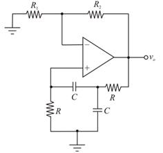
For the ideal operation amplifier, the inverting and non-inverting terminal currents should be 0. The inverting and non inverting node voltages should be equal by the virtual ground concept.

Redrawing the above circuit:

  Microelectronics: Circuit Analysis and Design, Chapter 15, Problem 15.40P , additional homework tip  2

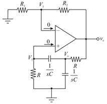
Applying Kirchhoff s current law at node Vx :

  VxV1R+Vx1 sC+VxV0R=0sC(VxV1)+sC(Vx)+VxV0R=0sRC( V x V 1 )+sRC( V x )+( V x V 0 )R=0sRC(VxV1)+sRC(Vx)+(VxV0)=0sRCVxsRCV1+sRCVx+VxV0=0(1+2sRC)VxsRCV1V0=0(1+2sRC)Vx=sRCV1+V0Vx=sRCV1+V01+2sRC

Hence,

  Vx=sRCV1+V01+2sRC

Applying Kirchhoff s current law at non-inverting node:

  V1Vx1 sC+V1R=0sC(V1Vx)+V1R=0sRC( V 1 V x )+V1R=0sRC(V1Vx)+V1=0sRC(V1Vx)+V1=0sRCV1+sRCVx+V1=0(1+sRC)V1sRCVx=0

Substituting Vx in the above equation:

  V1(1+sRC)sRC( sRC V 1 + V 0 1+2sRC)=0V1[( 1+sRC)( 1+2sRC)]sRC( sRC V 1 + V 0 )1+2sRC=0V1[(1+sRC)+(1+2sRC)]sRC(sRC V 1+V)0=0V1[1+2sRC+1sRC+2s2R2C2]s2R2C2V1sRCV0=0V1[1+2sRC+1sRC+2s2R2C2s2R2C2]=sRCV0V1[1+3sRC+s2R2C2]=sRCV0V1=sRCV01+3sRC+s2R2C2V1V0=sRCs2R2C2+3sRC+1

Therefore, the feed-back gain is given as:

  β(s)=V1V0=sRCs2R2C2+3sRC+1

Applying Kirchhoff s current law at inverting node:

  V1R1+V1V0R2=0R2V1+R1( V 1 V 0 )R1R2=0R2V1+R1(V1V0)=0R2V1+R1V1+R1V0=0(R1+R2)V1R1V0=0R1V0=(R1+R2)V1V0=( R 1 + R 2 R 1 )V1

Therefore,

  A(s)=V0V1=(1+R2R1)

The loop gain is known as the multiplication of the amplifier gain and the feedback transfer function gain as shown below:

  T(s)=A(s)β(s)T(s)=(1+ R 2 R 1 )( sRC ( sRC ) 2 +3sRC+1)T(s)=(1+ R 2 R 1 )( sRC s 2 R 2 C 2 +3sRC+1)

Therefore,

The transfer function is T(s)=(1+R2R1)(sRCs2R2C2+3sRC+1) .

Put s=jω in the above transfer function:

  T(jω)=(1+ R 2 R 1 )( jωRC ( jω ) 2 R 2 C 2 +3jωRC+1)=(1+ R 2 R 1 )( jωRC ω 2 R 2 C 2 +j3ωRC+1)T(jω)=(1+ R 2 R 1 )( jωRC 1 ω 2 R 2 C 2 +j( 3ωRC ))

Therefore,

  T(jω)=(1+R2R1)(jωRC1ω2R2C2+j( 3ωRC))

For frequency oscillation the real part should be 0:

  ω02=1R2C2ω0=1 R 2 C 2 ω0=1RC2πf0=1RCf0=12π1RCf0=12πRC

Therefore,

The frequency oscillation is f0=12πRC

For the oscillation, the imaginary part is equal to 1:

  1=(1+ R 2 R 1 )jωRCj3ωRC1=(1+ R 2 R 1 )133=1+R2R1R2R1=2

Therefore, R2R1=2

Want to see more full solutions like this?

Subscribe now to access step-by-step solutions to millions of textbook problems written by subject matter experts!
Students have asked these similar questions
R₁ 22 ΚΩ VIN- R₂ www 220 ΚΩ -VOUT Figure 15.4: A non-inverting amplifier circuit. Consider the op amp circuit in figure 15.4 for the following: 1. If the op amp has a gain bandwidth of 220 kHz, what will the bandwidth of the whole amplifier circuit be?
B- An rate. analog signal having single frequency as 3 kHz is sampled with 5 kHz S Describe its frequency spectrum. What will be the output if the sampled signals a passed through a low-pass filter having cutoff frequency at 2.5 kHz? signal. are sent in the analog
- at A signal Flt) = 2e ult) is applied to the input of.. System have frequency trunsfer funchiom THlw)I = Determine the required relations ibetween the Constants a und b Such that exactly 50% of the input energy on to the output %3D a 1-ohm basis is transffered

Chapter 15 Solutions

Microelectronics: Circuit Analysis and Design

Ch. 15 - Prob. 15.6TYUCh. 15 - Prob. 15.6EPCh. 15 - Redesign the street light control circuit shown in...Ch. 15 - A noninverting Schmitt trigger is shown m Figure...Ch. 15 - For the Schmitt trigger in Figure 15.30(a), the...Ch. 15 - Prob. 15.9TYUCh. 15 - Prob. 15.8EPCh. 15 - Prob. 15.9EPCh. 15 - Consider the 555 IC monostablemultivibrator. (a)...Ch. 15 - The 555 IC is connected as an...Ch. 15 - Prob. 15.10TYUCh. 15 - Prob. 15.11TYUCh. 15 - Prob. 15.12TYUCh. 15 - Prob. 15.12EPCh. 15 - Prob. 15.13EPCh. 15 - (a) Consider the bridge amplifier in Figure 15.46...Ch. 15 - Prob. 15.14EPCh. 15 - Prob. 15.15EPCh. 15 - Prob. 15.16EPCh. 15 - Prob. 1RQCh. 15 - Prob. 2RQCh. 15 - Consider a lowpass filter. What is the slope of...Ch. 15 - Prob. 4RQCh. 15 - Describe how a capacitor in conjunction with two...Ch. 15 - Sketch a onepole lowpass switchedcapacitor filter...Ch. 15 - Explain the two basic principles that must be...Ch. 15 - Prob. 8RQCh. 15 - Prob. 9RQCh. 15 - Prob. 10RQCh. 15 - Prob. 11RQCh. 15 - What is the primary advantage of a Schmitt trigger...Ch. 15 - Sketch the circuit and explain the operation of a...Ch. 15 - Prob. 14RQCh. 15 - Prob. 15RQCh. 15 - Prob. 16RQCh. 15 - Prob. 17RQCh. 15 - Prob. 18RQCh. 15 - Prob. D15.1PCh. 15 - Prob. 15.2PCh. 15 - The specification in a highpass Butterworth filter...Ch. 15 - (a) Design a twopole highpass Butterworth active...Ch. 15 - (a) Design a threepole lowpass Butterworth active...Ch. 15 - Prob. 15.6PCh. 15 - Prob. 15.7PCh. 15 - Prob. 15.8PCh. 15 - A lowpass filter is to be designed to pass...Ch. 15 - Prob. 15.10PCh. 15 - Prob. 15.11PCh. 15 - Prob. D15.12PCh. 15 - Prob. D15.13PCh. 15 - Prob. D15.14PCh. 15 - Prob. 15.15PCh. 15 - Prob. 15.16PCh. 15 - Prob. 15.17PCh. 15 - Prob. 15.18PCh. 15 - A simple bandpass filter can be designed by...Ch. 15 - Prob. 15.20PCh. 15 - Prob. 15.21PCh. 15 - Prob. D15.22PCh. 15 - Prob. 15.23PCh. 15 - Consider the phase shift oscillator in Figure...Ch. 15 - In the phaseshift oscillator in Figure 15.15, the...Ch. 15 - Consider the phase shift oscillator in Figure...Ch. 15 - Prob. 15.27PCh. 15 - Prob. 15.28PCh. 15 - Prob. 15.29PCh. 15 - Prob. 15.30PCh. 15 - Prob. 15.31PCh. 15 - A Wienbridge oscillator is shown in Figure P15.32....Ch. 15 - Prob. 15.33PCh. 15 - Prob. D15.34PCh. 15 - Prob. D15.35PCh. 15 - Prob. 15.36PCh. 15 - Prob. 15.37PCh. 15 - Prob. D15.38PCh. 15 - Prob. 15.39PCh. 15 - Prob. 15.40PCh. 15 - Prob. 15.41PCh. 15 - For the comparator in the circuit in Figure...Ch. 15 - Prob. 15.43PCh. 15 - Prob. 15.44PCh. 15 - Prob. 15.45PCh. 15 - Consider the Schmitt trigger in Figure P15.46....Ch. 15 - The saturated output voltages are VP for the...Ch. 15 - Consider the Schmitt trigger in Figure 15.30(a)....Ch. 15 - Prob. 15.50PCh. 15 - Prob. 15.52PCh. 15 - Prob. 15.53PCh. 15 - Prob. 15.54PCh. 15 - Prob. 15.55PCh. 15 - Prob. 15.56PCh. 15 - Prob. 15.57PCh. 15 - Prob. D15.58PCh. 15 - Prob. 15.59PCh. 15 - The saturated output voltages of the comparator in...Ch. 15 - (a) The monostablemultivibrator in Figure 15.37 is...Ch. 15 - A monostablemultivibrator is shown in Figure...Ch. 15 - Prob. D15.63PCh. 15 - Design a 555 monostablemultivibrator to provide a...Ch. 15 - Prob. 15.65PCh. 15 - Prob. 15.66PCh. 15 - Prob. 15.67PCh. 15 - Prob. 15.68PCh. 15 - An LM380 must deliver ac power to a 10 load. The...Ch. 15 - Prob. 15.70PCh. 15 - Prob. D15.71PCh. 15 - Prob. 15.72PCh. 15 - (a) Design the circuit shown in Figure P15.72 such...Ch. 15 - Prob. 15.74PCh. 15 - Prob. 15.75PCh. 15 - Prob. 15.76PCh. 15 - Prob. D15.77PCh. 15 - Prob. 15.78P
Knowledge Booster
Background pattern image
Electrical Engineering
Learn more about
Need a deep-dive on the concept behind this application? Look no further. Learn more about this topic, electrical-engineering and related others by exploring similar questions and additional content below.
Similar questions
SEE MORE QUESTIONS
Recommended textbooks for you
Text book image
Electricity for Refrigeration, Heating, and Air C...
Mechanical Engineering
ISBN:9781337399128
Author:Russell E. Smith
Publisher:Cengage Learning
What is Filter & Classification of Filters | Four Types of Filters | Electronic Devices & Circuits; Author: SimplyInfo;https://www.youtube.com/watch?v=9x1Sjz-VPSg;License: Standard Youtube License