
Concept explainers
Videos
a.
The expression for the frequency of the oscillation.
a.
Answer to Problem D15.38P
The oscillation frequency is
Explanation of Solution
Given:
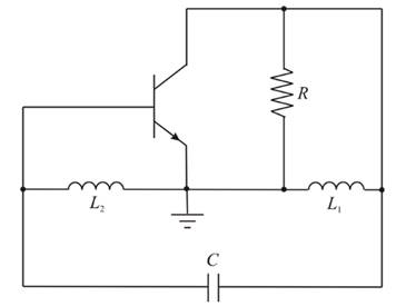
The circuit for the Hartley oscillator is given as:

Forward biased junction diffusion resistance is
Drawing the small signal equivalent of the Harley oscillato:
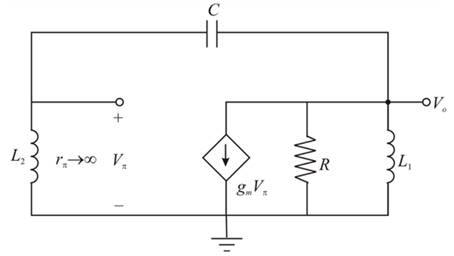
The output resistance
Applying the nodal analysis at the output node (
And the result by the voltage divider:
Solving equation (2) and equation (1):
Substituting s=
The condition for the oscillation indicates that the real and the imaginary components of the equation 4.
should be zero.
From the imaginary component, the oscillation frequency:
Hence, the oscillation frequency is
b.
To show: The condition for the oscillation is
b.
Explanation of Solution
Given:
The circuit for the Hartley oscillator is given as:
The real component of the equation 4 should be zero:
Therefore,
c.
To design: The circuit for oscillation at the given frequency.
c.
Explanation of Solution
Given:
The circuit for the Hartley oscillator is given as:

Frequency of oscillation is
Inductors is
The condition for oscillation:
Substituting
Hence,
The frequency of oscillation:
Hence,
Want to see more full solutions like this?
Chapter 15 Solutions
Microelectronics: Circuit Analysis and Design


- Q5 A given UJT with an intrinsic standoff ratio n= 0.6. If a 100µf capacitor is used to generate the timing pulses, calculate the timing resistor required to produce an .oscillation frequency of 110 Hz R Negative Pulse UJT E Va2 B2 B, R1 Positive Pulse OV 90.90 136.40 Οarrow_forwardA:11 A docs.google.com For positive half of the signal below, what is the peak output value of the circuit? NOTE: use silicon diode. * 20 V 10V -20 V O 3.3 O -10.3 50.7 29.3 32.3 like that of the clipper, the shape of the input signals of a clamper is changed. * O F От For the given circuit for a 40 V (p-p) sinusoidal input vi, what is the value of vi at which the clipping begIs: v-ov. NOTE: usearrow_forwardWhich of the following annot be said of an L-Ccircuit? a.Exponentially decaying time response b.Tank circuit c.Sinusoidal response d.Oscillatorarrow_forward
- Since the frequency of the Wien bridge oscillator circuit you see in the figure below is f= 15.915 kHz; b. The capacitor you found and the current capacitor values do not change, and the frequency is doubled. What should be done to remove it, explain by calculation? 100k 1 %3D 2n R1.C1.R2.C2 741 J+12 Vo 100k 10k 10nF 10karrow_forwardIn an LC oscillator, if the value of L is increased by four times, the frequency of oscillations is....arrow_forwardCalculate the oscillation frequency for the BJT Hartley oscillator circuit if LRFC =0.5 mH, L1 = 750 μH, L2 = 750 μH, M = 150 μH, and C = 150 pF. Show the details of your work. Write your solution on a white typewriting paper, scan it in JPEG format and upload it to the space provided below.arrow_forward
- Which of the following is not a part of the PLL O a. Loop filter O b. phase detector O C. Differentiator O d. Voltage controlled oscillator Which of the following statements is not correct: a. A third-order PLL can track a frequency step with zero steady-state error. O b. A first-order PLL can track a frequency step with a zero steady-state error. O c. A first-order PLL can track a phase step with a zero steady-state error. O d. A second-order PLL can track a frequency step with zero steady-state error. %24arrow_forward9. Determine the fundamental period of the following signal:sin20t. a) 1/60 sec b) 1/30 sec c) 1/20 sec d) a/30 sec 178% Start TOSHIBA ESC B/O F1 F2 F3 F4 F5 F6 F7 11 3 r 4 8A9arrow_forwardA carrier signal of 12 V amplitude is modulated by an Bhutananahuhu information signal to a depth of 90%. Calculate the Vmax and Vmin for the modulated wave. tututututuarrow_forward
- A boost regulator has an input voltage of 8V. The average output voltage and current are respectively equal to 16V and SA. The switching frequency is 10 kHz. If L-100 uH and C-300 uF, then the ripple current of the inductor delta (1) and the peak current of the inductor would be respectively equal to: Select one: O a. 4A 12A O b. 4A. 8A O C BA, 16A O d. 8A, 12Aarrow_forwardI want to design an oscillator for a PWM supply. It will run with a square wave of 75 KHz. Voltage is 15VDuty Cycle about 50%. Hint: Choose values of resistor, and then calculate capacitor for the frequency. Draw the circuit. Show the calculations.arrow_forwardHome Work 1/ what js meant by Nyquí st rate ? Q2/ what s meant by Pulse Moduletim ? why we need PM?arrow_forward
 Introductory Circuit Analysis (13th Edition)Electrical EngineeringISBN:9780133923605Author:Robert L. BoylestadPublisher:PEARSON
 Delmar's Standard Textbook Of ElectricityElectrical EngineeringISBN:9781337900348Author:Stephen L. HermanPublisher:Cengage Learning
 Programmable Logic ControllersElectrical EngineeringISBN:9780073373843Author:Frank D. PetruzellaPublisher:McGraw-Hill Education
 Fundamentals of Electric CircuitsElectrical EngineeringISBN:9780078028229Author:Charles K Alexander, Matthew SadikuPublisher:McGraw-Hill Education
 Electric Circuits. (11th Edition)Electrical EngineeringISBN:9780134746968Author:James W. Nilsson, Susan RiedelPublisher:PEARSON
 Engineering ElectromagneticsElectrical EngineeringISBN:9780078028151Author:Hayt, William H. (william Hart), Jr, BUCK, John A.Publisher:Mcgraw-hill Education,