
Concept explainers
Videos
Design an ideal inverting op-amp circuit such that the voltage gain is
(a)
The value of the resistance
Answer to Problem 9.1EP
Thevalue of the resistance
Explanation of Solution
Calculation:
The given diagram is shown in Figure 1
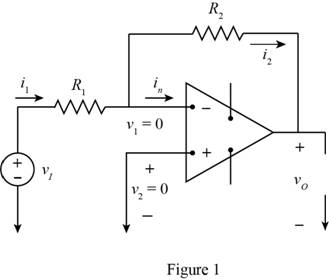
The above op-amp is considered to be ideal.
The value of the voltage
The expression for the input voltage is given by,
Substitute
Apply KCL at negative terminal.
Substitute
The expression for the value of the voltage gain is given by,
The expression for the value of the current
Substitute
Substitute
Substitute
Substitute
Substitute
Substitute
The expression for the maximum value of the current is given by,
The expression for the maximum current is given by,
Substitute
The expression for the minimum value of the resistance
Substitute
The expression for the minimum value of the resistance
Substitute
Conclusion:
Therefore, the value of the resistance
(b)
The value for the range of the output voltage
Answer to Problem 9.1EP
The range of the output voltage is
Explanation of Solution
Calculation:
The expression for the variation of the output voltage is given by,
From above the variation of the voltage is given by,
Conclusion:
Therefore, the range of the output voltage is
Want to see more full solutions like this?
Chapter 9 Solutions
Microelectronics: Circuit Analysis and Design
Additional Engineering Textbook Solutions
Electrical Engineering: Principles & Applications (7th Edition)
Programmable Logic Controllers
ANALYSIS+DESIGN OF LINEAR CIRCUITS(LL)
Basic Engineering Circuit Analysis
Principles and Applications of Electrical Engineering
ELECTRICITY FOR TRADES (LOOSELEAF)


- 8. For the op amp circuit below: a. Calculate ₁ b. What is the Gain of this circuit? c. Calculate Vout d. Calculate Inf 4V + 15 ΚΩ Rs 27 ΚΩ Rf + V I outarrow_forward1. (2 pts) An inverting op amp circuit is shown. Find vo. a. b. What is the current in? C. What are the voltages vn and vp at the (-) and (+) inputs? 3 V 3kQ 4- Un + Up 12 ΚΩ 15 V -ISV + vo 6 kN Voarrow_forwardVin R₁ www R₂ www Vout For the given op amp circuit, calculate Vout if R₁ = R2 = 100 2 and vin = 8 V. The value of the output voltage is * V.arrow_forward
- A silicon photodiode is connected to an op-amp as indicated. Under an illuminance of 500 lux, the photocurrent Ip is 80 nA. I R = 1MQ w out Write down the values of 11, 12 and Ip. From these values, deduce the output voltage. Briefly describe how this circuit works. c) Will this circuit work under sunlight? The illuminance of sunlight is about 100,000 lux. You may assume the photocurrent respond linearly with incident light flux, and the op-amp is powered between 9V alkaline cell. (i.e., V+ = 9V, V¯ at ground).arrow_forward294 227 The op amp in the crout in the figure is ideal. (Figure 1) The de signal source has a value of 860 mV Figure 1630 ww 24301 w ISV 15 V 102> Part A Find the Thevenin voltage of the equivalent circuit (Eigure 2) with respect to the output terminals a, b Express your answer with the appropriate units. Vn Submit Part RD- -11.55 Submit Part C X Incorrect, Try Again: 2 attempts remaining 4 Previous Answers Request Answer Find the Thevenin resistance of the equivalent circuit with respect to the output terminals a, b, Express your answer with the appropriate units Value V Value C 4 n What is the output resistance of the invertingamp Express your answer with the appropriate units. Units 03 ? ? Units PPearson ?arrow_forwardFor the op amp circuit shown below, what is Vout for the V1 plot shown. Plot the results: (Provide your calculations and reasoning for your answer.) U1 Vout OUT OPAMP C1 R1 2u 10k V1 Input Voltage to Circuit 4 3.5 3 2.5 2 15 0.5 > -05 0 20 10 15 25 30 -1 -15 -2 -2.5 -3 -3.5 -4 Time (msec) %24 (A) TAarrow_forward
- 5 mv 25 ΚΩ o WWW R ww + If the op-amps are ideal and working in the linear range, R = 125 khoms, the output of the above circuit isarrow_forwardA "RL circuit" with 18ohm resistor and a 0.30 Henry inductor. If it has an initial current of 1 amp, what would the current will be after 0.017 sec?arrow_forwardFor the following circuits, determine and sketch the output waveforms given the input waveforms shown. Provide calculations and/or sufficient explanations to support your drawings. a) Circuit A: 6V Ideal - 20V + V V, R Vo -20V b) Circuit B: C 20V Ideal R 8V V -20V +arrow_forward
- 3. DERIVE THE TIME AND FREQUENCY DOMAIN MODEL OF THE NON-INVERTING OP-AMP SHOWN IN THE SCHEMATIC DIAGRAM BELOW. NOTE: INPUT: v₂ (t) or V₁(s) OUTPUT: v(t) or V. (s) R₁ = 10kΩ C₁ = 1nF R₂ = 50kn C₂ = 1nF Vi(t) R1 C1 $ C2 R2 Vo(t) PLOT THE SYSTEM TIME RESPONE AND FREQUENCY RESPONSE.arrow_forwardQuestion The saturation voltage of the ideal op-amp shown is ±10V. The output voltage vo of the following circuit in the steady-state is 0.25 µF 1 ΚΩ 10 V L 10 V 2kQ2 3 2 ΚΩ Voarrow_forwardThe arrow on the schematic symbol for a MOSFET indicates the channel material type. Select one: O True O False son The output of an op-amp comparator will be zero when both inputs are equal. Select one: of O True O False cion Which of the following current equations is true? Windos su of h lo le = 16 = Is ING D 40) ^ f4 f6 GD 19 O f2 f3 15 f7 18 (2) %23 & 3 E for GY K B Y N T of alt 61arrow_forward
 Introductory Circuit Analysis (13th Edition)Electrical EngineeringISBN:9780133923605Author:Robert L. BoylestadPublisher:PEARSON
 Delmar's Standard Textbook Of ElectricityElectrical EngineeringISBN:9781337900348Author:Stephen L. HermanPublisher:Cengage Learning
 Programmable Logic ControllersElectrical EngineeringISBN:9780073373843Author:Frank D. PetruzellaPublisher:McGraw-Hill Education
 Fundamentals of Electric CircuitsElectrical EngineeringISBN:9780078028229Author:Charles K Alexander, Matthew SadikuPublisher:McGraw-Hill Education
 Electric Circuits. (11th Edition)Electrical EngineeringISBN:9780134746968Author:James W. Nilsson, Susan RiedelPublisher:PEARSON
 Engineering ElectromagneticsElectrical EngineeringISBN:9780078028151Author:Hayt, William H. (william Hart), Jr, BUCK, John A.Publisher:Mcgraw-hill Education,