
Concept explainers
Videos
Assume the op-amps in Figure P9.6 are ideal. Find the voltage gain
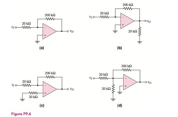
(a)
The voltage gain
Answer to Problem 9.6P
The value of the voltage gain is
Explanation of Solution
Calculation:
The given diagram is shown in Figure 1
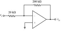
Mark the values and redraw the circuit of part (a).
The required diagram is shown in Figure 2
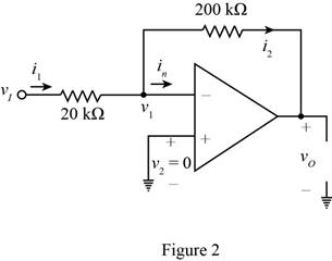
The from the above circuit the expression for the value of the voltage
Substitute
The value of the current
The expression for the value of the voltage gain is given by,
Apply KCL at the negative terminal.
Substitute
The expression for the value of the current
Substitute
Substitute
Substitute
The expression for the value of the input resistance is given by,
Substitute
Conclusion:
Therefore, the value of the voltage gain is
(b)
The voltage gain
Answer to Problem 9.6P
The value of the voltage gain is
Explanation of Solution
Calculation:
Mark the values and redraw the circuit of part (b).
The required diagram is shown in Figure 3
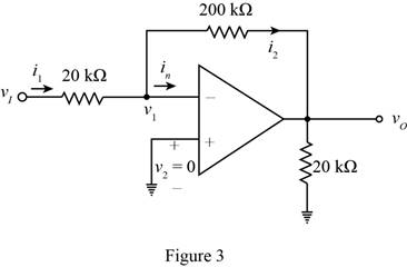
The from the above circuit the expression for the value of the voltage
Substitute
The value of the current
The expression for the value of the voltage gain is given by,
Apply KCL at the negative terminal.
Substitute
The expression for the value of the current
Substitute
Substitute
Substitute
The expression for the value of the input resistance is given by,
Substitute
Conclusion:
Therefore, the value of the voltage gain is
(c)
The voltage gain
Answer to Problem 9.6P
The value of the voltage gain is
Explanation of Solution
Calculation:
Mark the values and redraw the circuit of part (c).
The required diagram is shown in Figure 4
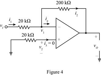
The from the above circuit the expression for the value of the voltage
Substitute
The value of the current
The expression for the value of the voltage gain is given by,
Apply KCL at the negative terminal.
Substitute
The expression for the value of the current
Substitute
Substitute
Substitute
The expression for the value of the input resistance is given by,
Substitute
Conclusion:
Therefore, the value of the voltage gain is
(d)
The voltage gain
Answer to Problem 9.6P
The value of the voltage gain is
Explanation of Solution
Calculation:
Mark the values and redraw the circuit of part (d).
The required diagram is shown in Figure 5
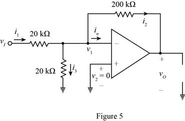
The from the above circuit the expression for the value of the voltage
Substitute
The value of the current
The expression for the value of the voltage gain is given by,
Apply KCL at the negative terminal.
Substitute
The expression for the value of the current is given by,
Apply KVL at the inverting terminal.
Substitute
Substitute
Substitute
The expression for the value of the input resistance is given by,
Substitute
Conclusion:
Therefore, thevalue of the voltage gain is
Want to see more full solutions like this?
Chapter 9 Solutions
Microelectronics: Circuit Analysis and Design


- 2. b) (i) Derive an expression for the differentiator using op-amp. (ii) Design a circuit to perform differentiation of an input signal that varies in frequency from 20HZ to about 2 KHz. (iii) If a sine wave of 0.5 V peak at 2 KHz is applied to the differentiator of part (ii), draw the output waveform.arrow_forwardIn an Inverting Op-Amp, how should I find the minimum output voltage value?arrow_forward2. What is a voltage-controlled voltage source? How can build this type of circuit by using an op-amp?arrow_forward
- If the ideal design for op-Amp circuit generate 200 mV at the output, Then practically with 26 mV offset voltage the output voltage of the circuit will be equal to .............. mVarrow_forward1- Mention any two advantages of Integrated Circuit . 2- For the circuit given below : Vin is a sine wave Vinpp=6 V and Vref=-2.4 V , Assume Vsat=±12V Name the circuit and draw the input and output waveforms . Vin Vref 3- Explain why open-loop op-amp configurations are not used in linear applications? Draw the block diagram of opamp and define the function of each blockarrow_forward10 V(p-p),1KHz sinusoidal voltage is applied to op-amp input and non-inverting input isgrounded. What is the gain of this op-amp and why?arrow_forward
- Consider the op-amp circuit to the right. Write a general formula for Vout as a function of Vin and the parameters of the resistor and MOSFET. Make sure to pay attention to the orientation of the MOSFET, you may assume an ideal op-amp. Vin R1 om + Q1 Voutarrow_forwardQUESTION 3: The parameters of the two inverting op-amp circuits connected in cascade in Figure P9.16 are R1 = 11 k2, R2 = 78 kN, R3 = 18 kN, and R4 = 81 kN. For input voltage vị=-0.13 V, calculate vo1, vo, iz, and i4. 'oi (V) Format : 0.63779726829547 vo (V) i2 (HA) 14 (HA) Format : -6.9832445578297 Format : -98.827586356923 Format : 85.624732255563 R2 R4 R1 iz R3 i4 ww ola i voi Figure P9.16arrow_forwardWhat is the voltage on out node for given ideal op-amp.arrow_forward
- Answer the following questions a) What assumption do we make for an ideal op - amp? b) Explain what slew rate is why it is important characteristic for an op amp.arrow_forwarda) What is an Op-Amp, and how is it used? b) What is the equivalent circuit model for an op-amp? c) What is negative feedback, and why is it used in Op Amp Circuits?arrow_forwardWhat are the characteristics of an ideal op amparrow_forward
 Introductory Circuit Analysis (13th Edition)Electrical EngineeringISBN:9780133923605Author:Robert L. BoylestadPublisher:PEARSON
 Delmar's Standard Textbook Of ElectricityElectrical EngineeringISBN:9781337900348Author:Stephen L. HermanPublisher:Cengage Learning
 Programmable Logic ControllersElectrical EngineeringISBN:9780073373843Author:Frank D. PetruzellaPublisher:McGraw-Hill Education
 Fundamentals of Electric CircuitsElectrical EngineeringISBN:9780078028229Author:Charles K Alexander, Matthew SadikuPublisher:McGraw-Hill Education
 Electric Circuits. (11th Edition)Electrical EngineeringISBN:9780134746968Author:James W. Nilsson, Susan RiedelPublisher:PEARSON
 Engineering ElectromagneticsElectrical EngineeringISBN:9780078028151Author:Hayt, William H. (william Hart), Jr, BUCK, John A.Publisher:Mcgraw-hill Education,