
Videos
In the circuit in Figure P9.81, assume that
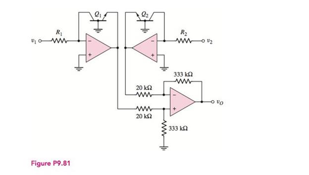
To show: The expression for the output voltageis
Explanation of Solution
Calculation:
The given diagram is shown in Figure 1.
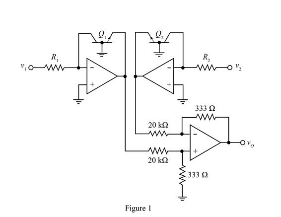
Mark the current directions, voltages and redraw the circuit.
The required diagram is shown in Figure 2
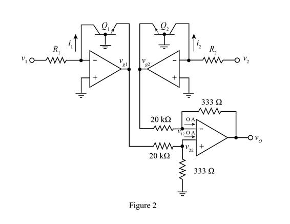
The expression for the voltage
For an ideal op-amp the voltage at both the input terminals are equal and is given by,
Substitute
Apply KCL at the inverting terminals of the lower op amp.
Substitute
The expression for the current
The expression for the current through the resistance
Substitute
The expression for the current
The expression for the current
Substitute
The expression for the transistor current is given by,
Substitute
Substitute
Substitute
Substitute
Therefore, theexpression for the output voltage is
Want to see more full solutions like this?
Chapter 9 Solutions
Microelectronics: Circuit Analysis and Design
Additional Engineering Textbook Solutions
Programmable Logic Controllers
Electrical Engineering: Principles & Applications (7th Edition)
Basic Engineering Circuit Analysis
Electric machinery fundamentals
Electric Circuits (10th Edition)
ELECTRICITY FOR TRADES (LOOSELEAF)


- a) Draw the basic topology of a buck converter. b) Design a buck converter to produce an output voltage of 18 V across a 10 2 load resistor. The output voltage ripple must not exceed 0.5 percent. The de supply is 48 V. Design for continuous inductor current. Specify the duty ratio, the switching frequency, the values of the inductor and capacitor, the peak voltage rating of each device, and the rms current in the inductor and capacitor. Assume ideal components.arrow_forwardComplete SolutionDraw the waveform of the given clipper circuit and determine the following: a.) At 0V, what is the output voltage?b.) At +20V, what is the output voltage?c.) At -5V, what is the output voltage?arrow_forwardEX3) Design a boost converter to provide an output voltage of 36V from a 24 V source. The load is 50 W. The voltage ripple factor must be less than 0.5%. Specify the duty cycle ratio, switching frequency, inductor and capacitor size, and power device.arrow_forward
- A high voltage engineer cascades 6 stages of a voltage doubler circuit to analyze effectiveness of doing so. Each capacitor in the circuit is 15 nF, of the input Asupply is 100 kv at Frequency 100 Hz. . so this voltages not enough with one moudle.So How much moudle can be in cascades fashion if the load current is 1 mA.arrow_forward4. The average power consumed by a resistance is equal to .. in non- .... ... sinusoidal input signal. *arrow_forwardQ9. Draw Zener regulator circuit to obtain regulated DC voltage 6.8 V. Considering input DC voltage in the range from 10V to 30V. Consider load resistance of 110KQ. Q10. Determine maximum and minimum value of Zener current if value of series resistance is 1 K, load resistance is 2KN and input varies from 10V to 30V. Zener voltage is 5 V. Q11. What is LED?arrow_forward
- A single-phase full-wave converter in the figure below is supplied with a 120-V, 60-Hz source. The load is highly inductive and the load current is continuous and free of ripples. The electromotive force is neglected (E = 0) and the resistance has a value of R = 10 2. The average output voltage is 85% of the maximum possible average output voltage. The delay angle would be equal to: Select one: 81.8° O b. 31.8° O c 67.8° O d. 51.8° AT₁ AT, R L +7=4₂ Warrow_forwardInput voltage VI is a DC signal. Do not repost other solutions to similar questions. Thank you.arrow_forwardReferring to the output voltage waveform below, find the following:arrow_forward
- A step down converter has a load resistance R-0.5Ohms, an input voltage Vs-200V and a battery voltage E-OV. The average load current la-250A and the converter frequency is 1000 Hz. The value of the inductance L that would limit the maximum load ripple current to 5% of la, would be equal to: Select one: O a. 15 mH O b. None of these O c. 4 mH O d. 9 mHarrow_forwardA single-phase full-wave converter in the figure below is supplied with a 120-V, 60-Hz source. The load is highly inductive and the load current is continuous and free of ripples. The electromotive force is neglected (E 0) and the resistance has a value of R = 10 Q. The delay angle is equal to 31.8°. The average output current is 9.18A and the nth harmonic component is expressed as below. The harmonic factor (known as THD) would be equal to: R 2. vZ.1. Ir = Vo n. T +Yi, = I, E Select one: O a. 58.3% Ob. 48.3% O C. 78.3% Od. 68.3%arrow_forwardQ9. Draw Zener regulator circuit to obtain regulated DC voltage 6.8 V. Considering input DC voltage in the range from 10V to 30V. Consider load resistance of 10KΩarrow_forward
 Introductory Circuit Analysis (13th Edition)Electrical EngineeringISBN:9780133923605Author:Robert L. BoylestadPublisher:PEARSON
 Delmar's Standard Textbook Of ElectricityElectrical EngineeringISBN:9781337900348Author:Stephen L. HermanPublisher:Cengage Learning
 Programmable Logic ControllersElectrical EngineeringISBN:9780073373843Author:Frank D. PetruzellaPublisher:McGraw-Hill Education
 Fundamentals of Electric CircuitsElectrical EngineeringISBN:9780078028229Author:Charles K Alexander, Matthew SadikuPublisher:McGraw-Hill Education
 Electric Circuits. (11th Edition)Electrical EngineeringISBN:9780134746968Author:James W. Nilsson, Susan RiedelPublisher:PEARSON
 Engineering ElectromagneticsElectrical EngineeringISBN:9780078028151Author:Hayt, William H. (william Hart), Jr, BUCK, John A.Publisher:Mcgraw-hill Education,