
Videos
Let
(a)
The value of the voltages
for the input voltage
Answer to Problem 9.63P
The value of the voltage
Explanation of Solution
Calculation:
The given diagram is shown in Figure 1
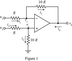
The expression for the value of the voltage
Apply KCL at the node
Substitute
Apply KCL at the node
Substitute
Substitute
The expression for the current
Substitute
Substitute
Substitute
The expression for the current
Substitute
Substitute
Substitute
Substitute
Substitute
Substitute
Substitute
Substitute
Substitute
Conclusion:
Therefore, the value of the voltage
(b)
The value of the voltages
Answer to Problem 9.63P
The value of the voltage
Explanation of Solution
Calculation:
Substitute
Substitute
Substitute
Substitute
Substitute
Substitute
Substitute
Conclusion:
Therefore, the value of the voltage
(c)
The value of the voltages
Answer to Problem 9.63P
The value of the voltage
Explanation of Solution
Calculation:
Substitute
Substitute
Substitute
Substitute
Substitute
Substitute
Substitute
Conclusion:
Therefore, the value of the voltage
Want to see more full solutions like this?
Chapter 9 Solutions
Microelectronics: Circuit Analysis and Design


- QUESTION 3: The parameters of the two inverting op-amp circuits connected in cascade in Figure P9.16 are R1 11 kN, R2 = 78 kN, R3 = 18 k2, and R4= 81 k. For input voltage v7=-0.13 V, calculate vo1, vo i2, and i4. Voi (V) vo (V) iz (LA) Format : 0.63779726829547 Format : -6.9832445578297 Format : -98.827586356923 14 (µA) Format : 85.624732255563 R2 R4 R1 iz R3 10a Figure P9.16arrow_forward0 ind the minimum value of R; in the circuit shown in Figure P9.50 for which the output voltage remains at just 5.6 V. 1,800 2 18 V RL Vout Vz= 5.6 Varrow_forwardQ9. Draw Zener regulator circuit to obtain regulated DC voltage 6.8 V. Considering input DC voltage in the range from 10V to 30V. Consider load resistance of 10KΩarrow_forward
- QUESTION 3: The parameters of the two inverting op-amp circuits connected in cascade in Figure P9.16 are R1 = 11 k2, R2 = 78 kN, R3 = 18 kN, and R4 = 81 kN. For input voltage vị=-0.13 V, calculate vo1, vo, iz, and i4. 'oi (V) Format : 0.63779726829547 vo (V) i2 (HA) 14 (HA) Format : -6.9832445578297 Format : -98.827586356923 Format : 85.624732255563 R2 R4 R1 iz R3 i4 ww ola i voi Figure P9.16arrow_forwardQuestions: Draw output waveform for the following circuits if sinusoidal signal of 6V peak-to-peak with zero offset is applied at the input. Consider reference voltage VR = +2V R. VR Consider Zener voltage 2.5V Dz * R VR = -3V v,(f) 22arrow_forwardOne way to measure the slew-rate limitation of an op amp is to apply a sine wave (or square wave) as the input to an amplifier and then increase the frequency until the output waveform becomes triangular. Suppose that a 1-MHz input signal produces a triangular output waveform having a peak-to-peak amplitude of 4 V. Determine the slew rate of the op amp.arrow_forward
- Problem 9.63 , except with R=1kOhm and a 100 Ohm load resistor from the op amp output pin to ground. Also find iofor each set of input conditions.arrow_forwardA single-phase full-wave converter in the figure below is supplied with a 120-V, 60-Hz source. The load is highly inductive and the load current is continuous and free of ripples. The electromotive force is neglected (E 0) and the resistance has a value of R = 10 Q. The delay angle is equal to 31.8°. The average output current is 9.18A and the nth harmonic component is expressed as below. The harmonic factor (known as THD) would be equal to: R 2. vZ.1. Ir = Vo n. T +Yi, = I, E Select one: O a. 58.3% Ob. 48.3% O C. 78.3% Od. 68.3%arrow_forwardA boost converter is required to have an output voltage of 8 V and supply a load current of 1 A. The input voltage varies from 2.7 to 4.2 V. A control circuit adjusts the duty ratio to keep the output voltage constant. Select the switching frequency. Determine a value for the inductor such that the variation in inductor current is no more than 40 percent of the average inductor current for all operating conditions. Determine a value of an ideal capacitor such that the output voltage ripple is no more than 2 percent. Determine the maximum capacitor equivalent series resistance for a 2 percent ripple.arrow_forward
- P9.11. Find the net power delivered to the amplifier by the three de supply voltages shown in Figure P9.11. 15 V Vin Amplifier RL 15 V= 5V tiga v to bonm aguo botonoo s abaol o i W IA boo W e o lang nt Jallee |2 A Figure P9.11arrow_forward1) To measure the carotid pulse, a piezoelectric sensor is used. The equivalent impedance of the sensor and cable are modelled as a resistance (Req) and a capacitance (Ceq) (see figure 1) and measure at 4 GN and 1 nF respectively. What should the input resistance of the amplifier (Rin) be to have a frequency response higher than 0.05 Hz. Assume that the carotid pulse is a step function. V1 Req TW Ceq Rin Amplifier Figure 1 Circuit for question 1arrow_forwardA single-phase full-wave converter in the figure below is supplied with a 120-V, 60-Hz source. The load is highly inductive and the load current is continuous and free of ripples. The electromotive force is neglected (E = 0) and the resistance has a value of R = 10 2. The average output voltage is 85% of the maximum possible average output voltage. The delay angle would be equal to: Select one: 81.8° O b. 31.8° O c 67.8° O d. 51.8° AT₁ AT, R L +7=4₂ Warrow_forward
 Introductory Circuit Analysis (13th Edition)Electrical EngineeringISBN:9780133923605Author:Robert L. BoylestadPublisher:PEARSON
 Delmar's Standard Textbook Of ElectricityElectrical EngineeringISBN:9781337900348Author:Stephen L. HermanPublisher:Cengage Learning
 Programmable Logic ControllersElectrical EngineeringISBN:9780073373843Author:Frank D. PetruzellaPublisher:McGraw-Hill Education
 Fundamentals of Electric CircuitsElectrical EngineeringISBN:9780078028229Author:Charles K Alexander, Matthew SadikuPublisher:McGraw-Hill Education
 Electric Circuits. (11th Edition)Electrical EngineeringISBN:9780134746968Author:James W. Nilsson, Susan RiedelPublisher:PEARSON
 Engineering ElectromagneticsElectrical EngineeringISBN:9780078028151Author:Hayt, William H. (william Hart), Jr, BUCK, John A.Publisher:Mcgraw-hill Education,